CPU Virtualization
CPU virtualization is the most core part of system virtualization technology, because the CPU is the most core component in a computer, directly controlling the operation of the entire system. At the same time, memory access (memory virtualization) and I/O operations (I/O virtualization) also directly depend on the CPU, making CPU virtualization the core of system virtualization technology.
In the joint paper "Formal Requirements for Virtualizable Third Generation Architectures" by Gerald J. Popek and Robert P. Goldberg, three sufficient conditions for a VMM satisfying virtualization system architecture were proposed: equivalence, resource control, and efficiency. To meet these conditions, CPU virtualization uses the classic model "Trap & Emulate", implementing the virtual environment through Ring Compression:
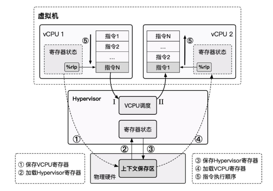
- The Hypervisor runs at the highest privilege level, and the Guest VM runs at a lower privilege level. The Guest VM directly executes non-sensitive instructions on the hardware. When the Guest VM encounters a sensitive instruction, it traps into the Hypervisor at the highest privilege level, which then emulates the behavior of the sensitive instruction.
- When a virtual CPU scheduling event occurs, we save the vCPU state, restore the Hypervisor state. After the Hypervisor completes its operations, it schedules the next virtual CPU, restoring the next vCPU's state and resuming execution.
Problems Encountered in x86 Virtualization
In the early stages of virtualization technology development, the x86 architecture, widely used in personal computing, did not provide good support for the classic virtualization architecture "Trap & Emulate". It had deficiencies in supporting system virtualization, and system virtualization could not be directly and effectively implemented.
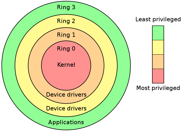
The Intel hierarchical protection rings divide privileges into ring0 through ring3, where the operating system kernel runs at ring0 privilege and user processes run at ring3 privilege.
In the classic system virtualization architecture "Trap & Emulate", the Guest OS runs entirely in ring3. When sensitive instructions are involved, the VM triggers a General Protection exception, which is intercepted and handled by the VMM. However, not all sensitive instructions are privileged instructions, and not all sensitive instructions have the opportunity to trigger an exception for the VMM to intervene. The x86 architecture has a total of 17 non-privileged sensitive instructions:
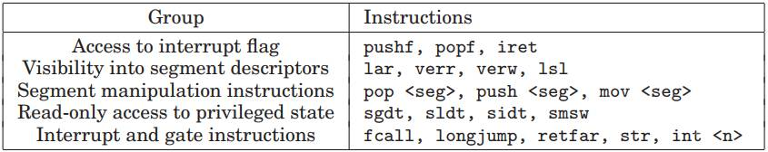
These instructions directly violate the Popek and Goldberg virtualization requirements, making x86 a non-virtualizable architecture.
For example, when we want to use popf under x86 to modify the interrupt flag (IF) in eflags, if we perform this operation in user mode, it will be silently ignored by the hardware without causing an exception, preventing the VMM from intervening.
"When hardware falls short, software fills the gap." Therefore, before hardware provided sufficient virtualization support, Hypervisors had to work at the software level, leading to two pure software virtualization techniques: "Emulation" (VMWare) and "Direct Source Code Rewriting" (Xen).
After software virtualization technology had matured for many years, x86 architecture support for virtualization finally arrived: "Hardware-Assisted Virtualization" (Intel VT) began to appear.
Pure Software CPU Virtualization
As previously noted, the x86 architecture has non-privileged sensitive instructions, which directly prevent the VMM from intercepting the x86 VM's sensitive behavior. This violates the Popek and Goldberg virtualization requirements. Therefore, before hardware virtualization support appeared, virtualization vendors had to start from the software level.
Emulation & Interpretation
"Emulation" technology actually predates virtualization. Pure software emulation is essentially writing application programs that exhibit the same behavior as the emulated object, thereby achieving the effect of running applications from non-homogeneous platforms.
Emulation technology can be applied not only at the program level but also at the system level: the essential behavior of CPU execution is to continuously fetch instructions from the memory region pointed to by the PC register, decode them, and execute them. It is not hard to imagine that the simplest and most straightforward way to implement a virtual machine is to emulate the behavior corresponding to each instruction, making the VM's behavior fully controllable by the VMM.
The principle behind emulation technology is also the simplest — we can implement emulation through interpretation, where the emulator program continuously reads instructions from memory and emulates the effect of each instruction. In a sense, each instruction completes a "trap" during execution. Therefore, we can use emulation technology to resolve virtualization gaps, and it can even emulate virtual machines with architectures different from the physical machine.
Qemu — Quick Emulator is essentially an emulator that completely emulates an entire computer system including various peripheral devices.
However, emulation technology based on interpretation has a very fatal drawback — extremely poor performance, because every instruction needs to be parsed by the VMM before being emulated. Even the simplest instruction may need to be broken down into multiple steps with multiple memory accesses, resulting in extremely low efficiency.
Let us revisit why we need emulation technology to implement virtual machines on x86 architecture: the existence of non-privileged sensitive instructions breaks the Popek and Goldberg virtualization requirements, but non-privileged sensitive instructions are only a minority — most instructions can still run directly on the physical hardware. Therefore, virtualization techniques improved upon emulation technology emerged: Scan & Patch and Binary Translation.
Scan & Patch
In virtualization scenarios, virtual machines mostly share the same ISA as the physical machine, so there is no need to adopt pure emulation technology. Instead, we can let non-sensitive instructions execute directly on the hardware and use some method to make non-privileged sensitive instructions trap into the VMM, thereby re-implementing the Trap & Emulate model.
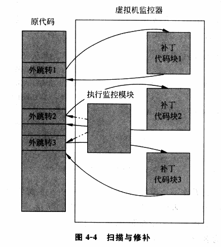
Scan & Patch is such a technique that lets non-sensitive instructions execute directly on the hardware while replacing sensitive instructions in the system code with jump instructions or other instructions that can trap into the VMM, so that when the VM executes sensitive instructions, it traps into the VMM, allowing the VMM to emulate the effect of the sensitive instructions.
The basic execution flow is as follows:
- The VMM scans each code segment before the VM executes it, parsing each instruction and looking for privileged and sensitive instructions.
- The VMM dynamically generates patch code for the corresponding instructions and replaces the original sensitive instructions with an outward jump to trap into the VMM, where the dynamically generated patch code is executed.
- After the patch code finishes execution, it jumps back to the VM to continue executing the next instruction.
In the "Scan & Patch" technique, most code can run directly on the physical CPU with minimal performance loss. However, "Scan & Patch" also has certain drawbacks:
-
Privileged and sensitive instructions are still completed through emulation, which may still cause some performance loss.
-
The code patches introduce additional jumps, which break code locality.
Locality principle: The memory locations accessed by the CPU for instructions/data tend to cluster in a small region.
- The VMM needs to maintain a copy of the original code corresponding to the patch code, which incurs additional overhead.
Binary Translation
To further improve virtualization performance, "Binary Translation" (BT) technology emerged. Similar to the "Scan & Patch" technique, binary translation also dynamically modifies code at runtime. However, the difference is that BT technology uses basic blocks (code blocks with only one entry and one exit) as the unit of translation:
- The Emulator translates the input binary code and outputs code composed of a subset of the corresponding ISA that contains no privileged or sensitive instructions, enabling it to run safely in user mode.
- The Emulator dynamically allocates a space for the current basic block to be executed, called the translation cache (TC), which stores the translated code. Each TC is associated with the original code through some mapping relationship (e.g., a hash table).
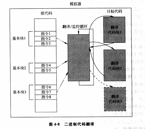
We can see that the principles of binary code translation and scan & patch techniques are largely very similar. However, binary code translation translates all code, while scan & patch only patches sensitive and privileged instructions. Additionally, scan & patch does not change the overall structure of the code — it only replaces sensitive and privileged instructions with instructions that trigger a trap into the VMM. In contrast, binary code translation directly changes the overall code structure of a basic block (for example, a basic block might be 40B before translation and 100B after translation, with the relative positions of internal code also changing).
Translation methods are roughly divided into the following two categories:
- Simple translation: This can be directly understood as equivalent code emulation. This method is relatively simple to implement but causes significant instruction count inflation.
- Identity translation: The original code and the resulting code are identical. In theory, most instructions can use identity translation to execute directly on the hardware, but this requires more complex dynamic analysis techniques.
On the same ISA architecture, most instructions can be directly identity-translated, except for the following types:
- PC-relative addressing instructions. The addressing of these instructions is related to the PC, but binary translation changes the structure of the code basic block, so these instructions need additional compensation code inserted to ensure accurate addressing, causing some performance loss.
- Direct control transfers. These instructions include function calls and jump instructions, whose target addresses need to be replaced with the addresses of the generated code.
- Indirect control transfers. These instructions include indirect calls, returns, and indirect jumps, whose target addresses are determined dynamically at runtime, so we cannot determine the jump target during translation.
- Privileged instructions. For simple privileged instructions, they can be directly translated to similar equivalent code (e.g., the cli instruction can be directly translated to setting the IF bit of the vCPU's flags register to 0). However, for slightly more complex instructions, deep emulation is needed, using jump instructions to trap into the VMM, which typically incurs some performance overhead.
For example, here is an example of basic block code translation in QEMU:
Since binary code translation uses a more complex process, it also introduces more issues. The following situations require additional handling:
- Self-Modifying Code (SMC). Such programs modify the code they execute at runtime, requiring our Emulator to re-translate the newly generated code.
- Self-Referential Code. Such programs read the contents of their own code segment during execution, requiring additional handling to ensure they read the original code segment contents rather than the translated code.
- Precise Exceptions. If an interrupt or exception occurs during the execution of translated code, the execution state needs to be restored to the state of the original code at the exception point before handing it over to the Guest OS. BT technology currently has difficulty handling this situation well, because the translated code and the original code have lost their one-to-one correspondence. A feasible solution is to roll back when an exception occurs and then re-execute using interpretation.
- Real-time Code. Such code has high real-time requirements, and running in an emulated environment loses timing precision. There is currently no solution for this.
Hardware-Assisted Virtualization
In this section, we use Intel VT-x as an example to introduce hardware-assisted virtualization technology.
Overview
Intel VT technology is the hardware support provided by Intel for x86 virtualization. The component that assists CPU virtualization is Intel VT-x technology, which extends the traditional IA32 processor architecture and provides hardware support for CPU virtualization on IA32 architecture.
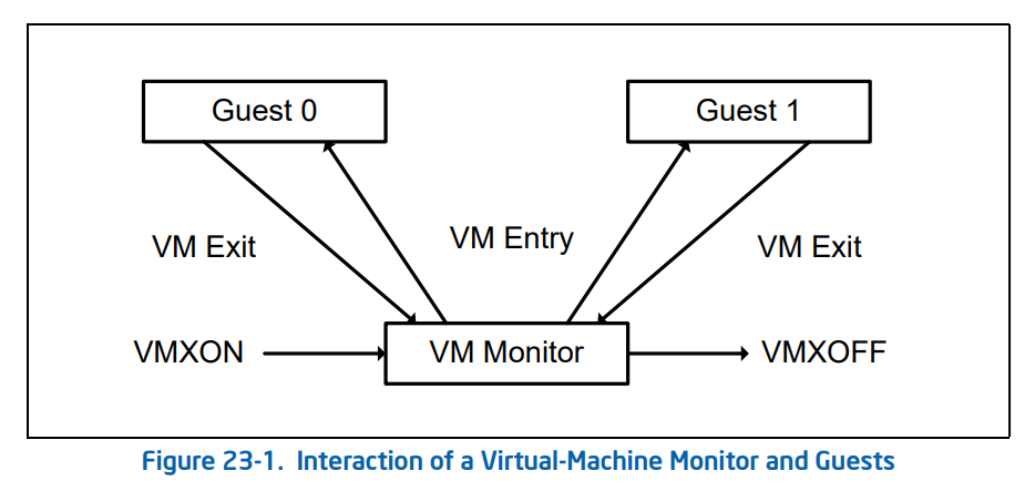
VT-x technology introduces two additional execution modes for Intel CPUs, collectively called VMX operation modes (Virtual Machine eXtensions), enabled through the vmxon instruction. These two execution modes each independently have their own hierarchical protection rings:
VMX Root Operation: The mode in which the Hypervisor operates. In this mode, all computer resources can be accessed, and VMs can be scheduled.VMX Non-Root Operation: The mode in which VMs operate. In this mode, only non-sensitive resources can be accessed. Access to sensitive resources (e.g., I/O operations) causes the CPU to exit Non-Root mode and trap into the Hypervisor, which handles the request and then re-enters Non-Root mode to resume VM execution.
From this, we define the switching behavior between Root mode and Non-Root mode:
VM-Entry: The Hypervisor saves its own state information, switches to VMX Non-Root mode, loads VM state information, and resumes the VM execution flow.VM-Exit: The VM pauses execution and saves its own state information, switches to VMX Root mode, loads Hypervisor state information, and executes the corresponding handler function.
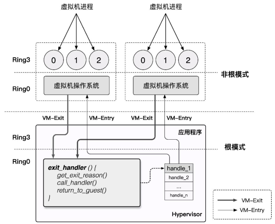
Since Non-Root mode and Root mode each have their own hierarchical protection rings, both the Host OS and Guest OS can run directly on the hardware in their respective modes without modification. Switching only occurs when the Guest OS accesses sensitive resources or when the Host OS schedules VMs. This ensures high VM performance while satisfying the Trap & Emulate model implementation, and also resolves the x86 architecture's virtualization gap.
VMCS
VMCS (Virtual-Machine Control Structure) is a block of memory used to store the relevant state needed for CPU virtualization. Each virtual CPU has a corresponding VMCS. At any given moment, a physical CPU can only be bound to one VMCS and vice versa. However, at different times, a VMCS can be bound to different physical CPUs, which is called VMCS migration.
The following two instructions are related to binding and unbinding VMCS:
| Instruction | Description |
|---|---|
| VMPTRLD | Binds the specified VMCS to the CPU executing this instruction |
| VMCLEAR | Unbinds the CPU executing this instruction from its VMCS |
In VT-x, the VMCS is defined as a memory block of at most 4KB that should be 4KB-aligned, with the following content format:
struct VMCS {
    /* Revision identifier, 4 bytes */
    uint32_t vmcs_revision_identifier:31, shadow_vmcs_indicator:1;

    /* Abort indicator, 4 bytes
     * A VMX abort is generated when VM-Exit fails, and the reason is stored here
     */
    uint32_t    vmx_abort_indicator;

    /* Data area */
    struct VMCSData vmcs_data;
};
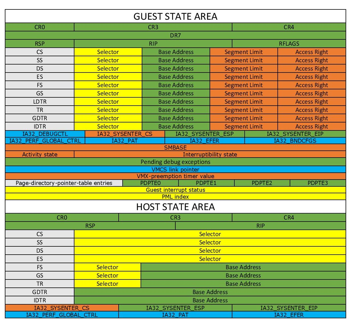
The VMCS data area stores the main information of the VMCS, divided into the following six sub-areas:
-
Guest-state area: Stores VM register state, loaded during VM-entry, saved during VM-exit.
-
Host-state area: Stores Hypervisor register state, loaded during VM-exit.
-
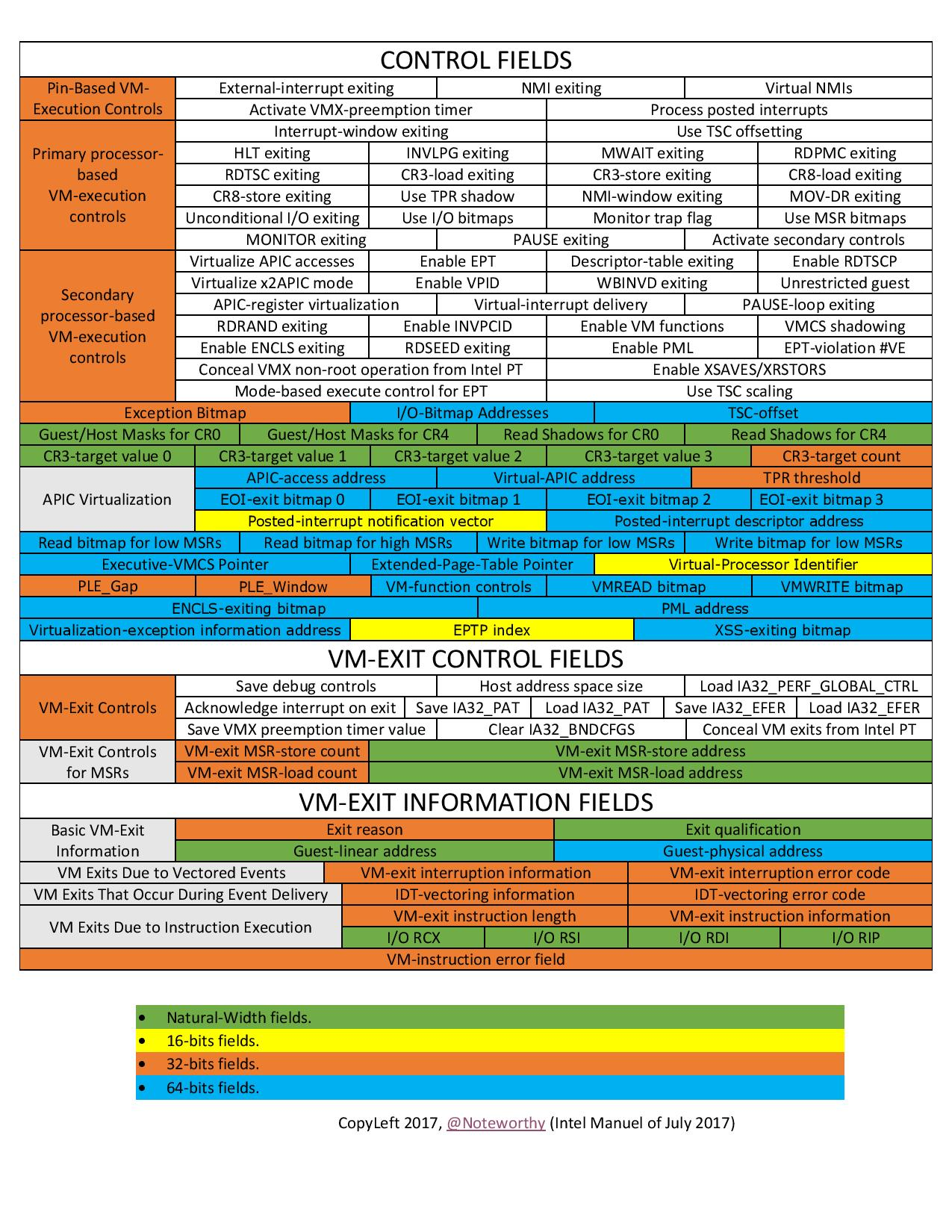
VM-execution control fields: Controls processor behavior in
Non-Rootmode. -
VM-entry control fields: Controls certain behavior during the
VM-Entryprocess. -
VM-exit control fields: Controls certain behavior during the
VM-Exitprocess. -
VM-exit information fields: Stores the basic reason for
VM-Exitand other detailed information. On some processors, this area is read-only.
We can read and write the VMCS through the following two instructions:
| Instruction | Description |
|---|---|
| VMREAD | Reads the field specified by "index" in the VMCS |
| VMWRITE | Writes data to the field specified by "index" in the VMCS |
The index here is not an offset value. Instead, Intel has defined a unique index value for each field in the data area. For example, the index value for the ES segment selector in the Guest State Area is
0x00000800.Of course, memorizing the indexes of all fields is not realistic. The best approach is to consult the reference tables frequently :) Recommended reading: Intel SDM, specifically Intel® 64 and IA-32 Architectures Software Developer's Manual Volume 3C: System Programming Guide, Part 3.
VMX Operation Modes
As an extension of the traditional IA32 architecture, VMX operation modes are disabled by default. Only when the VMM needs to use hardware-assisted virtualization functionality will it use two new instructions provided by Intel to enable or disable VMX operation modes:
VMXON: Enable VMX operation mode.VMXOFF: Disable VMX operation mode.
The VMX lifecycle as described in the Intel SDM is as follows:
- Software enters VMX operation mode through the
VMXONinstruction. - The VMM can enter the Guest VM through
VM entries(only one VM can be executed at a time). The VMM usesVMLAUNCH(first entry into the VM) andVMRESUME(resuming from the VMM to the VM) instructions to enableVM entry, and regains control throughVM exits. VM exitstransfer control through the entry points specified by the VMM. After the VMM responds to the VM exit reason, it returns to the VM throughVM entry.- When the VMM wants to stop itself and exit VMX operation mode, it uses the
VMXOFFinstruction to do so.
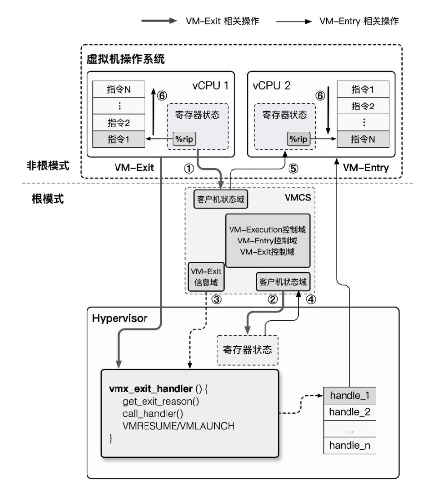
Now let us delve into the implementation details of VM entry and VM exit. During their respective processes, they perform the following actions:
- VM entry: Switching from the Hypervisor to the VM
- Check VMCS validity (whether the values of each field are valid).
- Load the fields from the VMCS
Guest-state areainto the corresponding registers. - Load the specified MSRs.
- Set the VMCS state to
launched. - Perform event injection (such as exceptions, asynchronous interrupts, etc.) to the VM as needed by writing to the VMCS
VM-entry Interruption-Information. - VM exit: Switching from the VM to the Hypervisor
- Write the VM exit reason and detailed information into the VMCS
VM-exit information fields. - Save the VM's registers to the VMCS
Guest-state area. - Restore Host registers from the VMCS
Host-state area. - Load the specified MSRs.
Here the author provides a supplementary concept: Model Specific Register, or MSR, is a set of registers under x86 used to control CPU operation, feature toggles, debugging, program execution tracing, and CPU performance monitoring.
For example, the
syscallinstruction obtains the kernel system call entry point through MSR registers.Each MSR register has an id, called the
MSR Index, which we can use to read and write specific MSR registers through theRDMSRandWRMSRinstructions.Detailed information about MSR registers can be found in Volume 4 of the Intel SDM.
KVM & QEMU-KVM
Kernel-based Virtual Machine is an open-source system virtualization kernel module integrated into the kernel since Linux 2.6.20. It is essentially a Hypervisor within the kernel that relies on hardware-assisted virtualization, or in other words, KVM turns the Linux kernel into a Hypervisor, and provides a corresponding user-space interface for operating VMs: /dev/kvm, which we can manipulate through ioctl commands.
However, KVM itself only provides CPU and memory virtualization and cannot constitute a complete virtualization environment. It is natural to think that we can reuse existing full virtualization solutions, delegating the work of emulating CPU and memory to KVM, thus directly leveraging hardware-assisted virtualization through KVM to improve virtual machine performance.
QEMU supports creating and running virtual machines through KVM. The QEMU + KVM virtualization scheme works as follows:
- QEMU enters kernel mode through ioctl, transferring control to KVM, which runs the VM.
- A VM-Exit occurs, KVM takes over, determines the reason, and decides whether to continue running or hand off to QEMU for handling.
- If the latter, control returns to user-space QEMU handler code for appropriate processing, after which it either exits or returns to the first step.
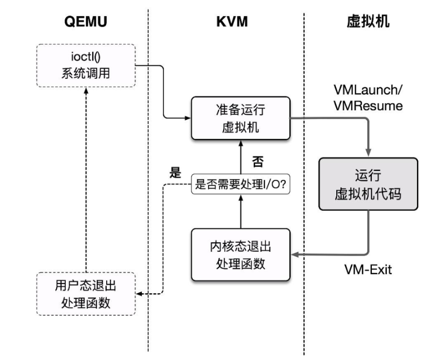
This basic execution framework corresponds to the kvm_cpu_exec() function in the QEMU source code accel/kvm/kvm-all.c:
int kvm_cpu_exec(CPUState *cpu)
{
    //...
    cpu_exec_start(cpu);

    do {
        //...
        /**
         * Start running the VM, essentially ioctl(kvm_fd, KVM_RUN)
         * When a VM-Exit occurs, it is first handled in KVM.
         * If IO is generated, it exits kernel mode, i.e., returns here,
         * and then proceeds to user-space handling.
         */
        run_ret = kvm_vcpu_ioctl(cpu, KVM_RUN, 0);

        //...
        if (run_ret < 0) {
            /**
             * A return value less than 0 indicates something went wrong
             * with the VM run. It is handled briefly here before breaking
             * out of the main loop.
             */
            //...
        }

        trace_kvm_run_exit(cpu->cpu_index, run->exit_reason);
        /* This is a large switch that handles different cases based on the exit reason. The complete code is omitted. */
        switch (run->exit_reason) {
        case KVM_EXIT_IO:
            DPRINTF("handle_io\n");
            /* Called outside BQL */
            kvm_handle_io(run->io.port, attrs,
                          (uint8_t *)run + run->io.data_offset,
                          run->io.direction,
                          run->io.size,
                          run->io.count);
            ret = 0;
            break;
        case KVM_EXIT_MMIO:
            DPRINTF("handle_mmio\n");
            /* Called outside BQL */
            address_space_rw(&address_space_memory,
                             run->mmio.phys_addr, attrs,
                             run->mmio.data,
                             run->mmio.len,
                             run->mmio.is_write);
            ret = 0;
            break;
        //...
        default:
            DPRINTF("kvm_arch_handle_exit\n");
            ret = kvm_arch_handle_exit(cpu, run);
            break;
        }
    } while (ret == 0);

    /* Execution finished, cleanup */
    // ...
REFERENCE
"System Virtualization: Principles and Implementation" — Intel Open Source Technology Center
【VIRT.0x02】Introduction to System Virtualization
Formal Requirements for Virtualizable Third Generation Architectures