Basic Knowledge
If you are not familiar with basic operating system theory, the author actually recommends starting from the open-source Linux kernel monolithic kernel. This article will basically not cover fundamental operating system concepts.
The Windows operating system's full name is Windows New Technology (abbreviated as Windows NT). It once claimed to use a micro kernel architecture, meaning most system components exist in user mode, with only essential components existing in kernel mode. However, in reality, Windows has now placed quite a lot of things in kernel mode, so the current NT kernel is more akin to a hybrid kernel.
In this article, we will mainly introduce the basic operating principles and some fundamental components of the 64-bit Windows NT kernel, primarily using Windows 10 as an example. Content related to 32-bit will not be covered.
For definitions of some Windows kernel structures, refer to this website
I. User Mode Components
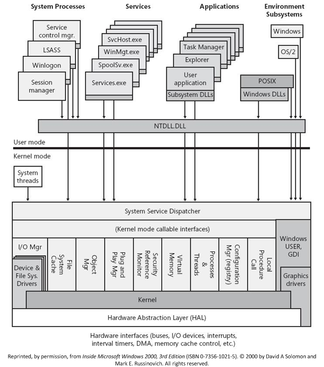
The Windows NT operating system is divided into four main parts in user mode:
- System Processes
- Services
- Applications
- Environment Subsystem
All user-mode programs in Windows ultimately need to go through the system call interfaces provided by ntdll.dll to access system resources.
II. Kernel Mode Components
The NT kernel does not have hardware-level layering (everything runs in ring0), but there is a conceptual layered dependency in its design, which can be divided into three layers as shown in the figure:
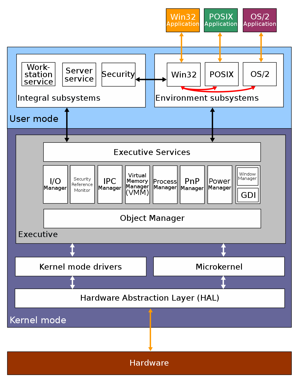
Upper Layer: Executive
The Executive is the core part of the NT kernel and is essentially the traditional operating system kernel itself. Some of the more critical subsystems include:
- Object Manager: The Object Manager is the underlying part of the Executive. In the kernel, all resources are objects, and the Object Manager is responsible for managing all kernel objects.
- I/O Manager: Responsible for receiving I/O requests from user-mode programs (such as disk access) and converting them into calls to the corresponding devices.
- Security Reference Monitor: Windows uses Access Control Lists (ACL) to determine object security, and this subsystem is responsible for enforcing security rules.
- IPC Manager: Responsible for handling communication requests between different processes.
- Virtual Memory Manager: Responsible for managing the entire operating system's memory at the kernel level.
- Process Manager: Responsible for the creation and destruction of processes and threads, but not responsible for direct scheduling.
- Plug and Play Manager: Responsible for detecting and providing corresponding services when devices are dynamically loaded or unloaded. Most of the actual implementation is in the user-mode
Plug and Play. - Power Manager: Responsible for handling power-related events (shutdown, sleep, etc.) and notifying the associated drivers.
- Graphic Device Interface: Responsible for all basic drawing functions. Since NT 4.0, it has been moved into kernel mode (previously in user mode).
The Executive's code resides in ntoskrnl.exe, and its interfaces exported to user mode are in ntdll.dll.
Middle Layer: (Micro)Kernel
The Kernel in the NT kernel is only responsible for the most basic hardware-side duties such as multi-processor synchronization, direct thread scheduling, and interrupt/exception dispatching, which aligns with the fundamental philosophy of the "micro kernel" architecture.
The Kernel's code resides in ntoskrnl.exe.
Middle Layer: Kernel Mode Drivers
Windows has two types of drivers: user-mode drivers and kernel-mode drivers. The latter provides corresponding interfaces to the former and passes data to lower-level drivers.
Kernel-mode drivers can be divided into three layers as shown in the figure. The closer to the bottom, the more closely tied to specific hardware structures:
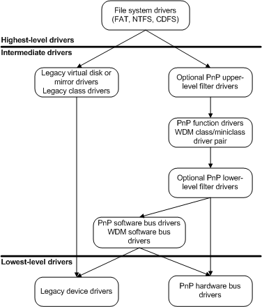
Kernel-mode drivers are implemented as discrete, modular components rather than being located in a specific PE file (somewhat like LKMs?).
Lower Layer: Hardware Abstraction Layer (HAL)
The Hardware Abstraction Layer (HAL) is responsible for hiding and masking the various details of different underlying hardware, thereby providing unified abstract hardware interfaces to the upper kernel layer, such as unified abstractions of hardware behaviors like IO interfaces and interrupt controllers.
The purpose of HAL is mainly to eliminate differences between hardware architectures, making it easier for operating system and driver developers to write code that is not strongly tied to specific hardware architectures for cross-platform execution, thus avoiding the need to write dedicated code for each hardware platform.
It should be noted that HAL is mainly responsible for abstracting general resources like IO. Some operations of certain drivers still bypass HAL and communicate directly with the hardware.
HAL-related code resides in hal.dll.
"Everything Is an Object"
Similar to the "everything is a file" philosophy in NIX systems, in the Windows NT kernel there is also the concept that everything is an object. Files, devices, synchronization mechanisms, registry keys, etc. are all represented as objects in the kernel*. Each object has a header that stores basic object information (such as name, type, location), and a body that stores data.
Objects in the NT kernel can be divided into two categories:
- Executive Objects: Resource objects exposed externally by the Executive (such as processes, threads, files, etc.), visible to user mode.
- Kernel Objects: The most basic resource objects (such as physical devices, etc.), not visible to user mode.
I. _OBJECT_HEADER: Object Basic Information
In the NT kernel, the _OBJECT_HEADER structure is used to store basic object information, defined as follows:
kd> dt nt!_OBJECT_HEADER
   +0x000 PointerCount     : Int8B
   +0x008 HandleCount      : Int8B
   +0x008 NextToFree       : Ptr64 Void
   +0x010 Lock             : _EX_PUSH_LOCK
   +0x018 TypeIndex        : UChar
   +0x019 TraceFlags       : UChar
   +0x019 DbgRefTrace      : Pos 0, 1 Bit
   +0x019 DbgTracePermanent : Pos 1, 1 Bit
   +0x01a InfoMask         : UChar
   +0x01b Flags            : UChar
   +0x01b NewObject        : Pos 0, 1 Bit
   +0x01b KernelObject     : Pos 1, 1 Bit
   +0x01b KernelOnlyAccess : Pos 2, 1 Bit
   +0x01b ExclusiveObject  : Pos 3, 1 Bit
   +0x01b PermanentObject  : Pos 4, 1 Bit
   +0x01b DefaultSecurityQuota : Pos 5, 1 Bit
   +0x01b SingleHandleEntry : Pos 6, 1 Bit
   +0x01b DeletedInline    : Pos 7, 1 Bit
   +0x01c Reserved         : Uint4B
   +0x020 ObjectCreateInfo : Ptr64 _OBJECT_CREATE_INFORMATION
   +0x020 QuotaBlockCharged : Ptr64 Void
   +0x028 SecurityDescriptor : Ptr64 Void
   +0x030 Body             : _QUAD
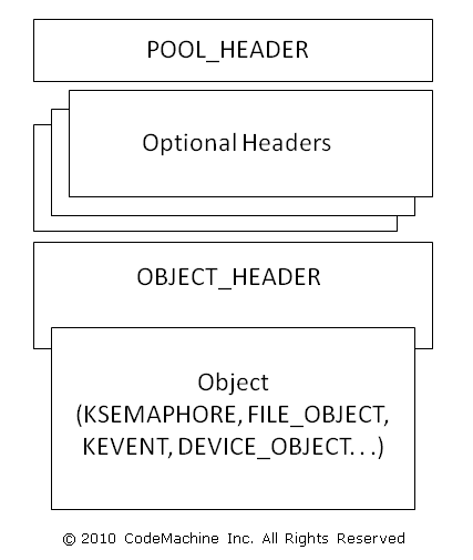
In addition to the fixed _OBJECT_HEADER, an object can also have additional optional headers to store extra information. Whether the corresponding optional header exists is determined by the _OBJECT_HEADER->InfoMask bitmask:
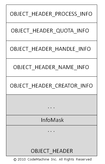
When a corresponding bit exists in the _OBJECT_HEADER->InfoMask bitmask, it indicates that the corresponding optional header exists. Since the storage order of optional headers is fixed, the NT kernel can easily calculate the offsets for different headers. The correspondence between bitmask and header type & size is as follows:
| Bit | Type | Size (on X86) |
|---|---|---|
| 0x01 | nt!_OBJECT_HEADER_CREATOR_INFO | 0x10 |
| 0x02 | nt!_OBJECT_HEADER_NAME_INFO | 0x10 |
| 0x04 | nt!_OBJECT_HEADER_HANDLE_INFO | 0x08 |
| 0x08 | nt!_OBJECT_HEADER_QUOTA_INFO | 0x10 |
| 0x10 | nt!_OBJECT_HEADER_PROCESS_INFO | 0x08 |
Before NT kernel version 19H1, the Windows kernel only used the Pool Allocator. At that time, each allocated kernel pool object had a _POOL_HEADER structure that stored relevant information:
kd> dt nt!_POOL_HEADER
   +0x000 PreviousSize     : Pos 0, 8 Bits
   +0x000 PoolIndex        : Pos 8, 8 Bits
   +0x002 BlockSize        : Pos 0, 8 Bits
   +0x002 PoolType         : Pos 8, 8 Bits
   +0x000 Ulong1           : Uint4B
   +0x004 PoolTag          : Uint4B
   +0x008 ProcessBilled    : Ptr64 _EPROCESS
   +0x008 AllocatorBackTraceIndex : Uint2B
   +0x00a PoolTagHash      : Uint2B
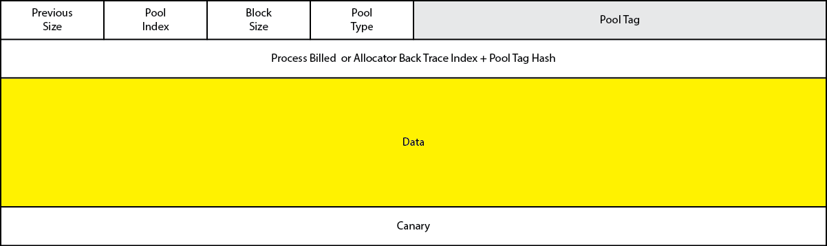
From this, we can derive the basic structure of a kernel object as shown in the figure below:
II. Object Manager and Namespaces
All objects in the NT kernel are managed through the Object Manager. User-mode access to any object must go through the Object Manager subsystem. The Object Manager is primarily responsible for the following tasks:
- Managing the creation and destruction of objects
- Maintaining the object namespace database
- Tracking resources allocated to processes
- Tracking access permissions for specific objects
- Managing object lifetimes
Objects belong to different namespaces. Different user sessions correspond to different namespaces. Objects are created in the current session's namespace by default. Additionally, there is a globally shared Global Namespace, which allows objects to be shared between different sessions.
When creating an object, you can use the
"Global\"prefix to create the object in the global namespace. For example, the following code creates an event object belonging to the global namespace:CreateEvent( NULL, FALSE, FALSE, "Global\\ARTTNBA3" );You can also use the
"Local\"prefix to explicitly specify that the object is created in the session namespace.
III. Handles
Somewhat similar to the concept of file descriptors in Linux, but extended to most kernel objects.
The Chinese translation "句柄" is rather unintuitive; personally the author feels translating it as reference descriptor might be more appropriate.
A handle is an object descriptor used by user-mode programs in Windows to manage corresponding kernel objects. It is represented as an integer value (32/64-bit integer in 32/64-bit systems). User programs can access the corresponding kernel objects through the handles they own.
In Windows, there are several types of handle tables that store object information:
- All object handles in the Windows NT kernel are stored in a global handle table
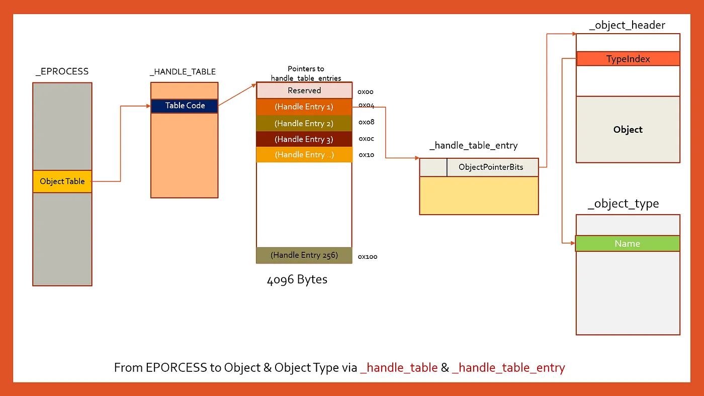
- Each process has its own independent handle table (its address is stored in the process control block at
_EPROCESS->_HANDLER_TABLE->TableCode). The object handle value obtained by a process is actually [the index of the corresponding entry in the table × 4] (64-bit system, each entry is 16 bytes)
The process handle table structure is shown in the figure below. Entry 0 is a reserved entry. The handle table entry is the _HANDLE_TABLE_ENTRY structure, whose lower 44-bit value shifted left by 4 bits plus 0xffff000000000000 gives the object header address:
In Windows 7, the process handle table simply stored object addresses, but in later kernel versions, things started to become more complex.
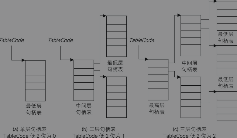
Additionally, TableCode uses the lower 4 bits to identify the structural level of the handle table — meaning the process handle table can actually have multiple levels of structure, similar to page tables. Only the last level stores object addresses; all other levels store table addresses. Each table is 4096 bytes in size (one memory page):
Memory Management
Memory management is one of the most core parts of an operating system — not to be overlooked.
I. Physical Memory Management
Kernel Address Space Layout
First, here is an overview of the 64-bit NT kernel memory layout:
We won't be studying the 32-bit layout for now, since starting from Win11 everything is purely 64-bit.
| Start | End | Size | Description | Usage |
|---|---|---|---|---|
| FFFF080000000000 | FFFFF67FFFFFFFFF | 238TB | Unused System Space | Space that will not be used |
| FFFFF68000000000 | FFFFF6FFFFFFFFFF | 512GB | PTE Space | Region where page tables reside |
| FFFFF70000000000 | FFFFF77FFFFFFFFF | 512GB | HyperSpace | Used for temporary transit mappings |
| FFFFF78000000000 | FFFFF78000000FFF | 4K | Shared System Page | Shared memory space, mapped in every process (as kernel entry point?) |
| FFFFF78000001000 | FFFFF7FFFFFFFFFF | 512GB-4K | System Cache Working Set | Working set of the system cache |
| FFFFF80000000000 | FFFFF87FFFFFFFFF | 512GB | Initial Loader Mappings | Region used by the initial kernel loader |
| FFFFF88000000000 | FFFFF89FFFFFFFFF | 128GB | Sys PTEs | System page table entry region; virtual memory mapped by MDL and driver images reside here |
| FFFFF8a000000000 | FFFFF8bFFFFFFFFF | 128GB | Paged Pool Area | Paged memory region |
| FFFFF90000000000 | FFFFF97FFFFFFFFF | 512GB | Session Space | |
| FFFFF98000000000 | FFFFFa70FFFFFFFF | 1TB | Dynamic Kernel VA Space | Dynamic memory region |
| FFFFFa8000000000 | *nt!MmNonPagedPoolStart-1 | 6TB Max | PFN Database | Stores PFN-related information |
| *nt!MmNonPagedPoolStart | *nt!MmNonPagedPoolEnd | 512GB Max | Non-Paged Pool | Non-paged memory region (will not be swapped to disk) |
| FFFFFFFFFFc00000 | FFFFFFFFFFFFFFFF | 4MB | HAL and Loader Mappings | Region used by the Hardware Abstraction Layer and loader |
_MMPFN: Physical Page Frame
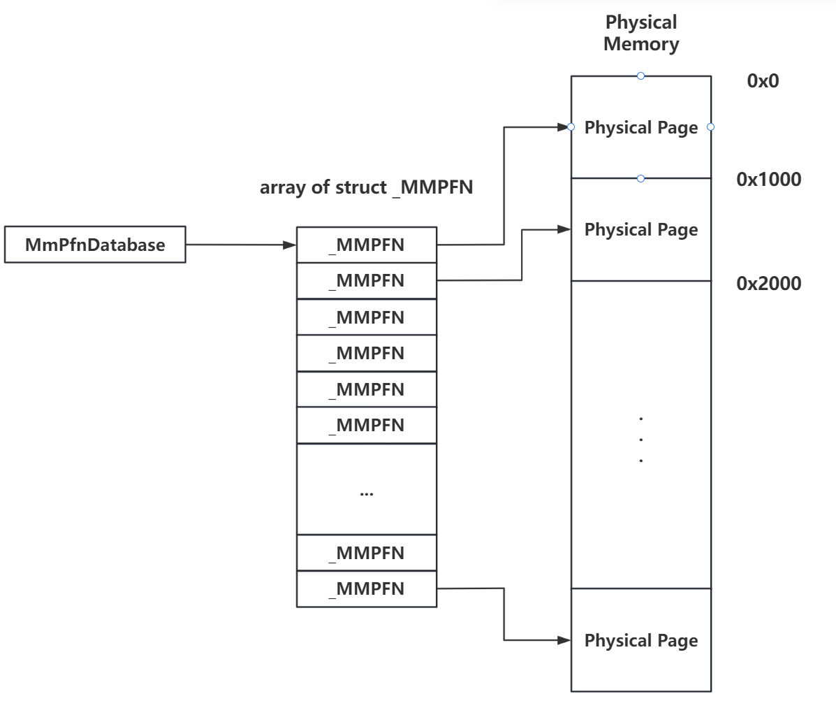
Similar to how the Linux kernel uses an array of page structures to represent physical memory, the NT kernel uses the _MMPFN structure to represent a single physical page, and manages all physical memory pages through a structure array. The array index is the page's Page Frame Number (PFN). This array is the PFN Database region, and the global pointer variable _MMPFN* MmPfnDatabase stores the address of this array:
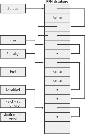
Depending on the different uses of pages, the _MMPFN for non-active pages is placed into different linked lists, with the list head being the _MMPFNLIST structure:
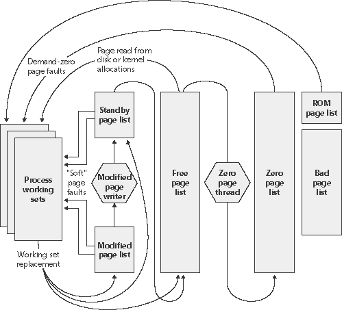
MmZeroedPageListHead: Linked list of zeroed free pagesMmFreePageListHead: Regular free page list. When the system is idle, pages are taken from this list, zeroed, and then placed ontoMmZeroedPageListHeadMmStandbyPageListHead: When a process discards pages from its working set (i.e., the set of pages in a process's virtual address space that reside in physical memory), if the page has not been modified it is placed in this list. Pages are allocated from this list when both the free list and zeroed list are emptyMmModifiedPageListHead: When a process discards pages from its working set, if the page has been modified and needs to be written back to disk, it is placed in this list. After the modified page writer completes the operation, pages are placed on the standby listMmModifiedNoWritePageListHead: When a process discards pages from its working set, if the page has been modified but does not need to be written back to disk, it is placed in this list. After the modified page writer completes the operation, pages are placed on the standby listMmBadPageListHead: These pages may have some faults
There are two reasons a process discards pages from its working set: one is that the existing working set is full and new pages need to be brought in, and the other is that the memory manager has trimmed its working set (e.g., when memory is running low).
When a process exits, all of its pages go into the free page list.
An overview of pages cycling between different lists:
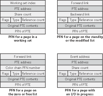
The _MMPFN structure also makes extensive use of unions. When pages cycle between different lists, fields at different offsets in _MMPFN have different meanings:
Page Bitmap
Under construction.
II. Pool Memory (before 19H1)
The Windows NT kernel divides pages into different "pools" based on their usage and further subdivides these pages into finer-grained small objects for kernel components. There are three types of pools in total:
- Non-Paged Pool: Pages in this pool permanently reside in physical memory and will not be swapped out to disk
- Paged Pool: Pages in this pool may be swapped out to disk when memory is tight
- Session Paged Pool: Pages in this pool may be swapped out to disk when memory is tight, with isolation between different sessions
Basic Unit: Pool Block
Each memory allocation in pool memory is called a pool block, similar to a chunk in ptmalloc2. Each pool block has a header at the beginning of its data that stores the following information:
- Previous Size: The result of right-shifting the size of the adjacent lower-address pool block by 4 bits
- Pool Index: The index of the pool descriptor group to which the pool block belongs; multiple pool descriptors form a pool descriptor array
- Block Size: The result of right-shifting the pool block size by 4 bits
- Pool Type: The type of pool to which the pool block belongs
- Pool Tag: Characters used for identification during debugging
- (A Union):
- Process Billed: Pointer to the
_EPROCESSprocess descriptor that allocated this pool block - (A structure)
- Allocator Back Trace Index:
- Pool Tag Hash:
- Process Billed: Pointer to the
Additionally, starting from Windows Server 2003, a Canary field was introduced at the tail of Pool Chunks to prevent potential chunk overflows. This value is checked during ( not much more information found yet; presumably during pool block allocation and deallocation ).
Note that Pool Chunks are only used for memory requests no larger than 4080 bytes (adding the 16-byte header makes exactly one memory page).
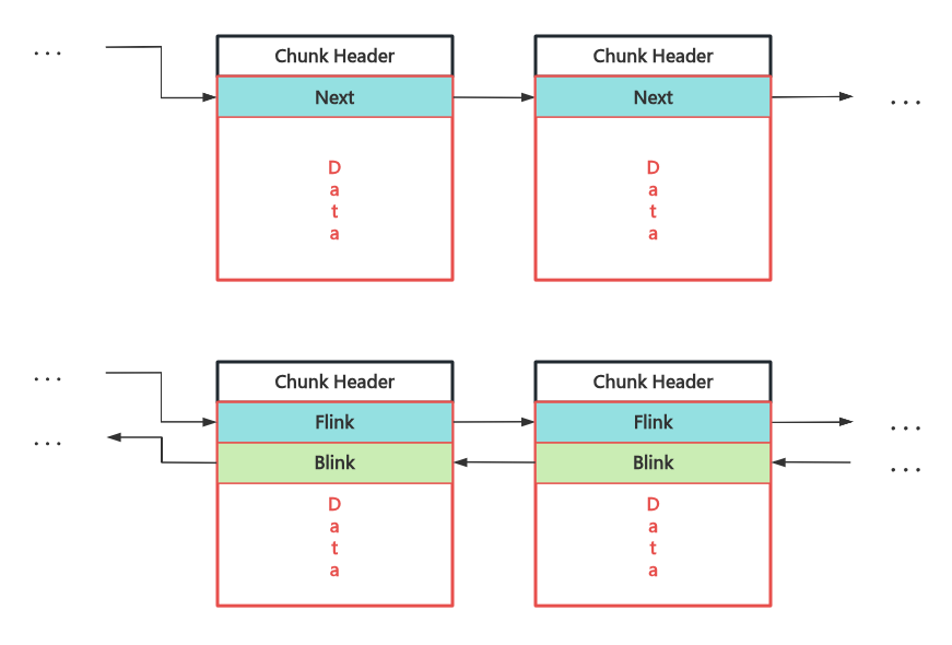
Pool Chunk management is very similar to ptmalloc2 chunk management. In the NT kernel, the Data field of Freed Chunks is reused to organize Free Chunks into singly or doubly linked lists:
Pool Descriptor: Kernel Shared Memory Pool
This structure has also undergone various changes across several versions of Windows 10, but the most critical change was from version 1809 to version 1903 (19H1). Starting from version 1903, the NT kernel introduced the Segment Heap mechanism as the kernel's dynamic memory allocator. Therefore, this section mainly covers 64-bit versions that still use the pool memory allocator up to and including version 1809.
Similar to kmem_cache in the Linux kernel, a single memory pool in the Windows kernel is represented by the _POOL_DESCRIPTOR structure, as shown in the figure below:
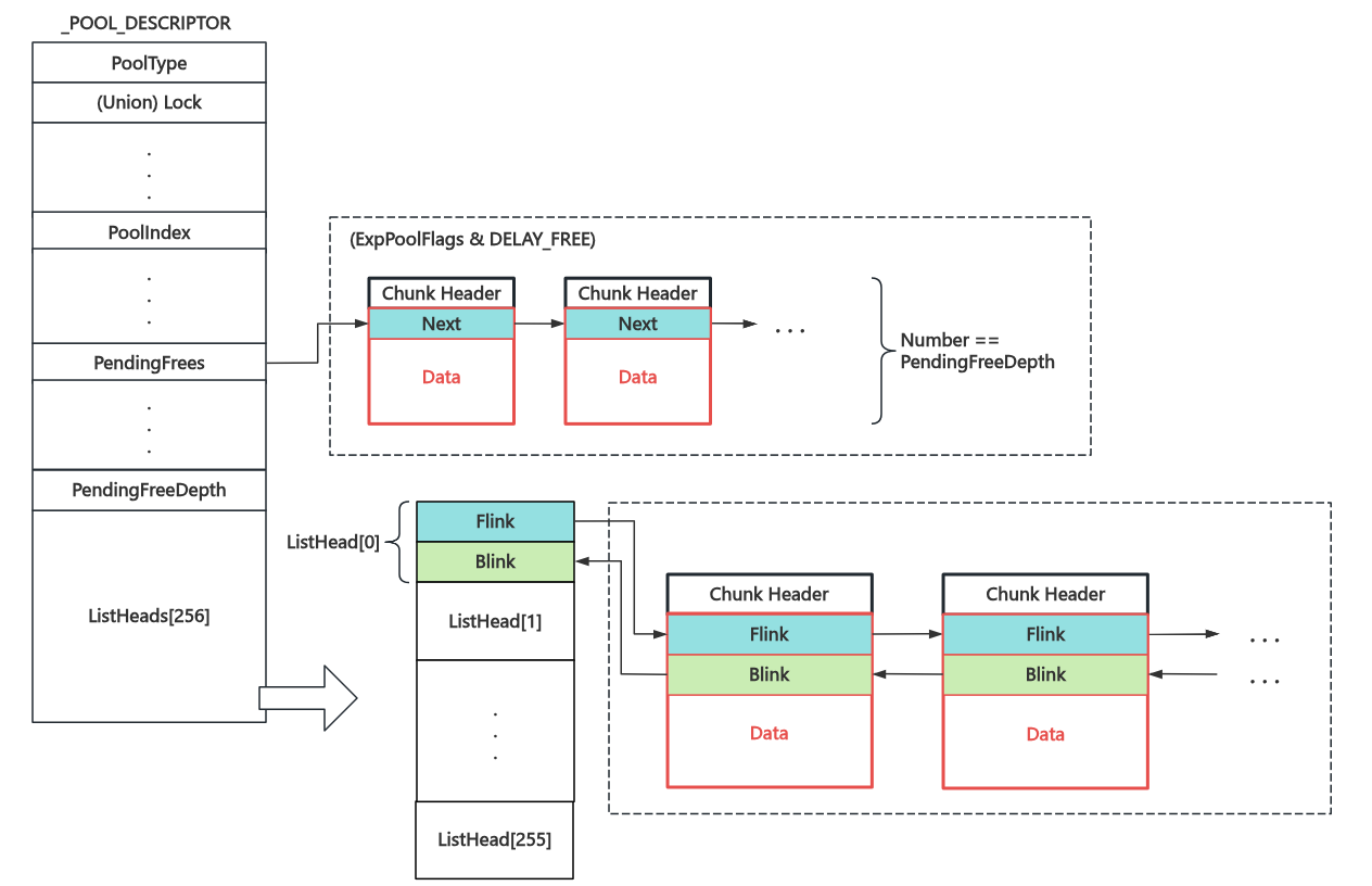
The memory pool corresponding to the pool descriptor is shared across the entire kernel. Two particularly important linked lists are:
- ListHeads linked list array: Stores regular freed pool blocks, connected via doubly linked lists. Blocks are placed into different sub-lists based on their size
- PendingFrees linked list: When the memory pool has the
DELAY_FREEflag set, freed pool blocks are first linked into this singly linked list (regardless of size). When the list depth exceeds a specified value, they are reclaimed in bulk
All initial memory pool descriptors are stored in the nt!PoolVector array.
Per-Core Exclusive Memory Pool: Lookaside Lists
The memory pool corresponding to pool descriptors is shared across all cores, and efficiency becomes disastrous when there are many cores. Therefore, each core actually has its own exclusive memory pool, stored in the Processor Control Region (the _KPCR structure, similar to the .percpu section in Linux) pointed to by the kernel-mode GS register — Lookaside Lists are used to prioritize handling the current core's pool memory requests. Only when they cannot satisfy the demand will memory be requested from the shared memory pool.
The structure of LookasideList is shown in the figure below. Based on size, items belong to different lists in the array. Each list is further divided into two sub-chains: a singly linked list (default, with a length limit, LIFO) and a doubly linked list (used when the former is full). The LookasideList array has fewer members and is therefore only used for smaller memory allocations.
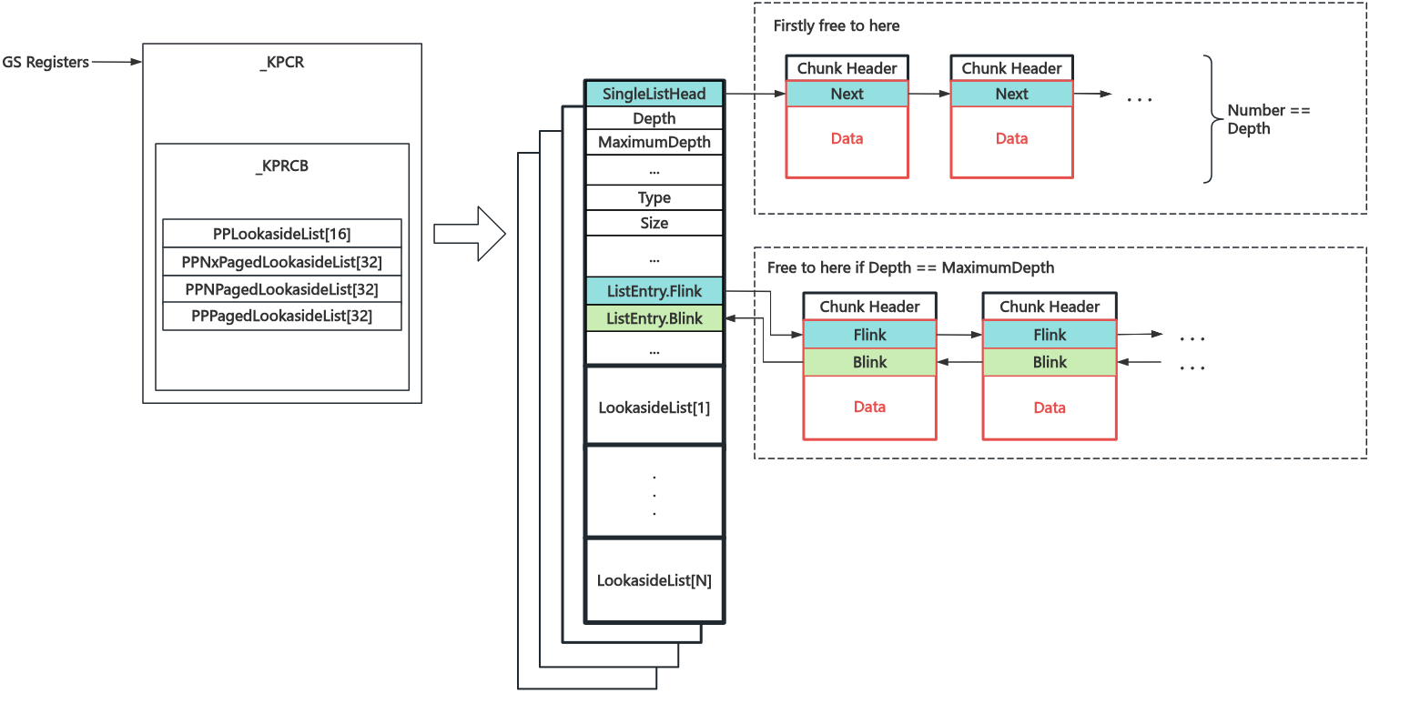
There are four types of LookasideLists (PP == Per Processor):
- PPLookasideList: LookasideList for frequently allocated and freed objects
- PPNxPagedLookasideList: LookasideList for non-executable pages in the non-paged pool
- PPNPagedLookasideList: LookasideList for the non-paged pool
- PPPagedLookasideList: LookasideList for the paged pool
What's the difference between PPLookasideList and other LookasideLists? The author doesn't know either
, waiting for the day Windows goes open source......
Basic Memory Allocation Algorithm
1. Memory Request Order
The core function for pool memory allocation is ExAllocatePoolWithTag(POOL_TYPE PoolType, SIZE_T NumberOfBytes, ULONG Tag). Users need to manually specify the pool type, required memory size, and other information. Kernel components and drivers typically use this API or higher-level wrappers to complete memory allocation requests in the kernel.
- General pool memory allocation is only applicable for memory requests smaller than 4080 bytes. For requests larger than this size,
nt!ExpAllocateBigPool()is internally used - First, an attempt is made to allocate memory from different lists in the LookasideList area of
_KPCRbased on the requested pool type. If it can be satisfied, it returns directly - If the LookasideList cannot satisfy the request, the corresponding pool is locked, and an attempt is made to allocate from the ListHeads list. If the allocated pool block is larger than needed, it is split into two blocks — one returned to the user and the other placed back on the ListHeads list
- If no pool blocks are available,
nt!MiAllocatePoolPagesis called to allocate memory pages, which are then split into two blocks — one returned to the user and the other placed back on the ListHeads list
2. Pool Block Splitting Method: Non-Page-Aligned Blocks Are Split from the Tail
When splitting a pool block, the kernel first checks the block's address. If it is aligned to the memory page size (0x1000), the user's required pool block is split from the head. Otherwise, the user's required pool block is split from the tail.
Basic Memory Deallocation Algorithm
The core function for pool memory deallocation is ExFreePoolWithTag(PVOID Entry, ULONG Tag). Kernel components and drivers typically use this API or higher-level wrappers to complete memory deallocation requests in the kernel.
The Chunk header contains the Pool Type & Index to which the Chunk belongs, so during deallocation, the belonging Pool and corresponding List can be determined directly. The specific deallocation flow is as follows:
- First, check if the Chunk is the first Chunk of a page (page-aligned). If so, attempt to call
nt!MiFreePoolPages()for reclamation. If successful, return directly - Next, check if the PrevSize of the physically adjacent higher-address Chunk equals the Size recorded in this Chunk's header. If not, an error is reported
- If the Size is smaller than a specific value, attempt to place it back into the corresponding Lookaside List
- If the corresponding Pool has the
DELAY_FREEflag set, place it back in the PendingFrees List (if PendingFreeDepth is greater than a specific value,nt!ExDeferredFreePoolis called first to empty the PendingFrees List) - Check the state of adjacent lower-address and higher-address Chunks, merge free blocks. Note that it will not merge with the head Chunk of the next memory page
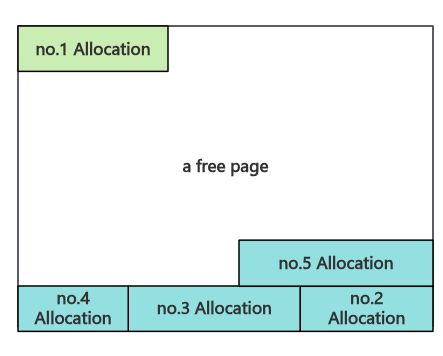
- Finally, check if the Page where the Chunk resides is a free page. If so, call
nt!MiFreePoolPages()for reclamation. Otherwise, place it back in the corresponding ListHeads list
III. Segment Heap in Kernel (from 19H1)
Starting from NT kernel version 19H1, the user-mode Segment Heap allocation logic was introduced into the kernel.
Under construction.
System Calls
I. System Call Path
Similar to system calls in Linux, the services provided by the kernel to user-mode processes in Windows are called system services. All system service calls go through ntdll.dll to complete the process of entering the kernel:
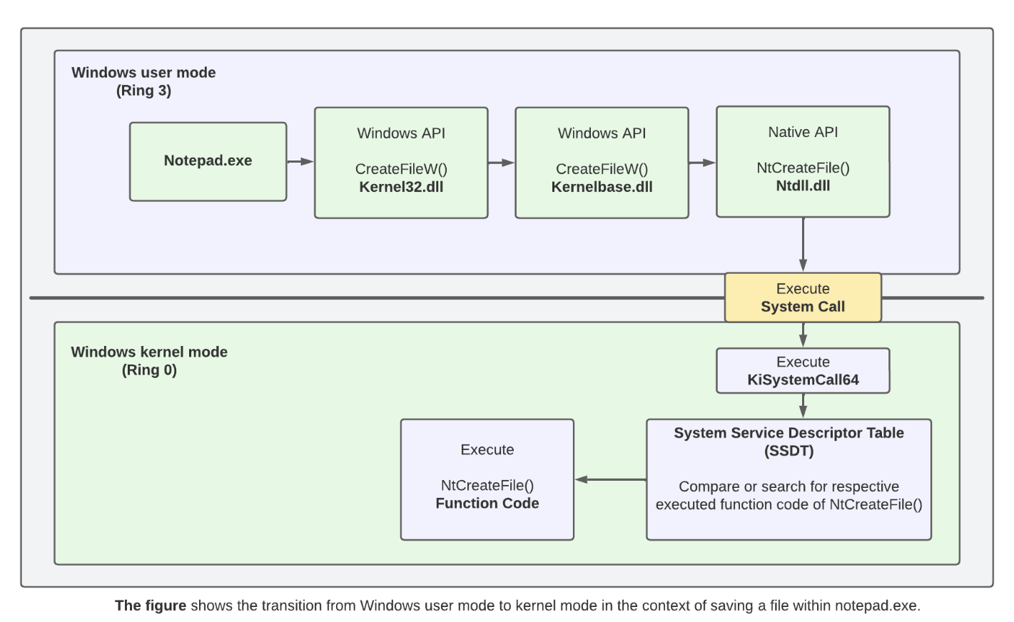
In
ntdll.dll, functions starting withNtand those starting withZware both system calls, essentially with no difference.
Taking the NtDeleteFile system service as an example: if the syscall instruction is supported, the kernel is entered via the syscall instruction; otherwise, the kernel is entered through the int 0x2E software interrupt via the interrupt gate:
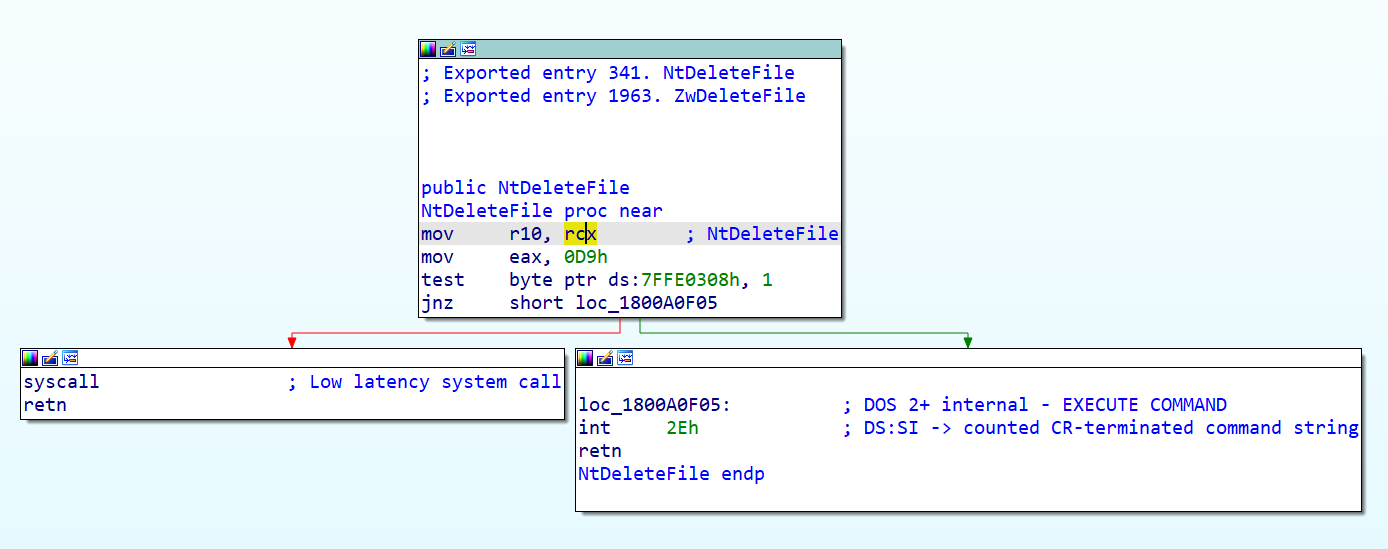
The
0x7FFE0000region is a memory area shared between the kernel and user processes (only the kernel has write permissions). It is aKUSER_SHARED_DATAstructure through which the kernel provides certain information to user mode.At offset
0x308, a boolean value is stored that indicates whether the architecture supports thesyscallinstruction.
The kernel-layer entry point for Windows system calls is set to the KiSystemCall64() function. When the syscall instruction / 0x2E software interrupt is executed, the CPU switches to ring0 and executes this function as the unified system call entry point. This function is defined in ntoskrnl.exe and calls the corresponding kernel function in the SSDT based on the system call number specified in the rax register.
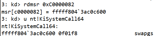
Note: Sometimes the system call entry is the
kiSystemCall64Shadow()function, but this function ultimately jumps to theKiSystemServiceUserlabel withinkiSystemCall64().
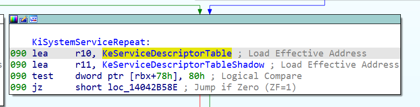
II. System Service Descriptor Table
SSDT Basic Structure
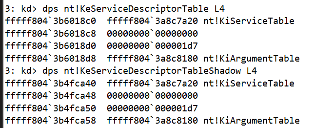
Reverse engineering the KiSystemCall64() function in ntoskrnl.exe, we notice that it references two variables: KeServiceDescriptorTable and KeServiceDescriptorTableShadow. These are the System Service Descriptor Tables (abbreviated as SSDT), used to store the system call functions corresponding to different system call numbers:
It is essentially a tag_SERVICE_DESCRIPTOR_TABLE structure, which is a structure array of four sub-tables of type SYSTEM_SERVICE_TABLE:
typedef struct tag_SERVICE_DESCRIPTOR_TABLE {
    SYSTEM_SERVICE_TABLE nt;        // KeServiceDescriptorTable only has this table
    SYSTEM_SERVICE_TABLE win32k;    // KeServiceDescriptorTableShadow additionally uses this table
    SYSTEM_SERVICE_TABLE sst3;
    SYSTEM_SERVICE_TABLE sst4;
} SERVICE_DESCRIPTOR_TABLE;
The SYSTEM_SERVICE_TABLE structure is defined as follows, where the ServiceTable member is the actual system call table:
typedef struct tag_SYSTEM_SERVICE_TABLE {
    PULONG      ServiceTable;   // The actual system call table
    PULONG      CounterTable;   //
    ULONG       ServiceLimit;   // Number of system calls
    PCHAR       ArgumentTable;  // Argument count table
} SYSTEM_SERVICE_TABLE;
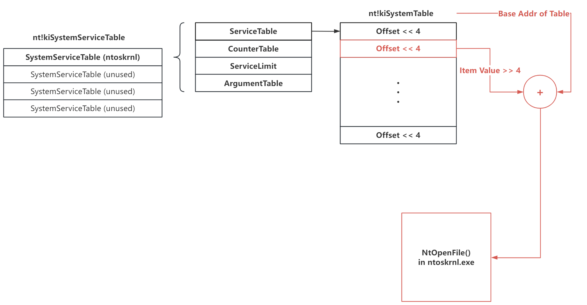
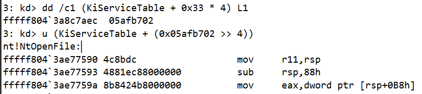
The ServiceTable member is actually a pointer to an array of [offsets from the target function to the system call table], with each entry being 4 bytes. However, during actual calculation, the value is first right-shifted by four bits before being added to the system call table start address to get the actual address of the system call: $$ Addr_{syscall} = Addr_{ServiceTable} + (ServiceTable[syscall_nr] >> 4) $$
From this, we derive the basic structure of the SSDT as shown in the figure below (using the NtOpenFile() system call as an example):
Verification in WinDbg:
The reasons for this mysterious left/right shift by 4 bits operation are as follows:
- For security considerations: This restricts the range of system calls reachable through the SSDT to within a 4GB offset near the SSDT. The spacing between driver address spaces is at least 4GB, and the SSDT address is hardcoded, which effectively prevents SSDT hijacking and increases attack difficulty.
- Storing the number of stack parameters: Many NT kernel system calls have far more than 6 parameters and thus require the stack for parameter passing. These 4 bits are used to record the number of parameters passed via the stack for each system call.
Shadow SSDT: The SSDT for GUI Programs
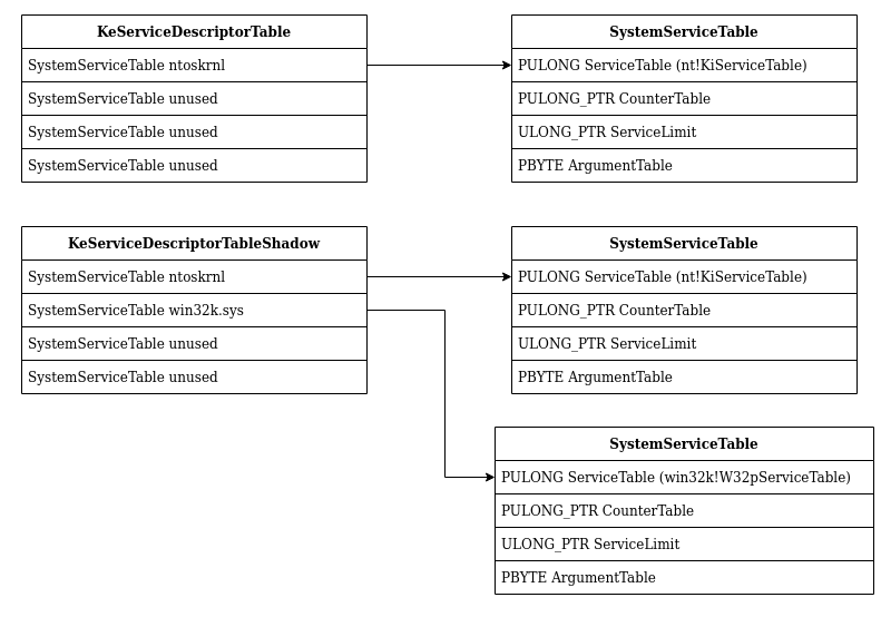
The Shadow System Service Descriptor Table (abbreviated as Shadow SSDT) is an SSDT dedicated to GUI programs. Compared to the regular SSDT, it has an additional sub-table W32pServiceTable responsible for graphics-related system calls, located in win32k.sys, i.e., the graphics subsystem:
Both the SSDT and Shadow SSDT share the same first sub-table
KiServiceTable, which corresponds to regular NT kernel system calls.
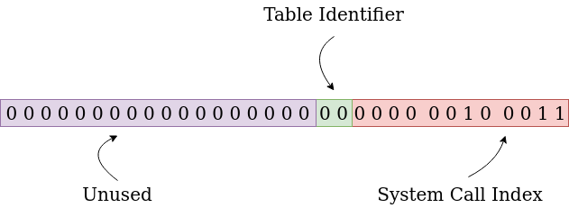
When an application makes a system call in Windows, the corresponding flag in the thread control block (KTHREAD) determines which master table is used. Bits 13-12 of the eax register are used to specify which sub-table to call, and the lower 12 bits specify the specific system call within the table:
Extended Reading: KeServiceDescriptorTableFilter
Starting from Windows 10, this table was introduced. When the
RestrictedGuiThreadflag is set in KTHREAD, this table replaces the Shadow SSDT. However, there is currently relatively little information available about this table (🕊)
Process Management
I. Processes and Threads in the NT Kernel
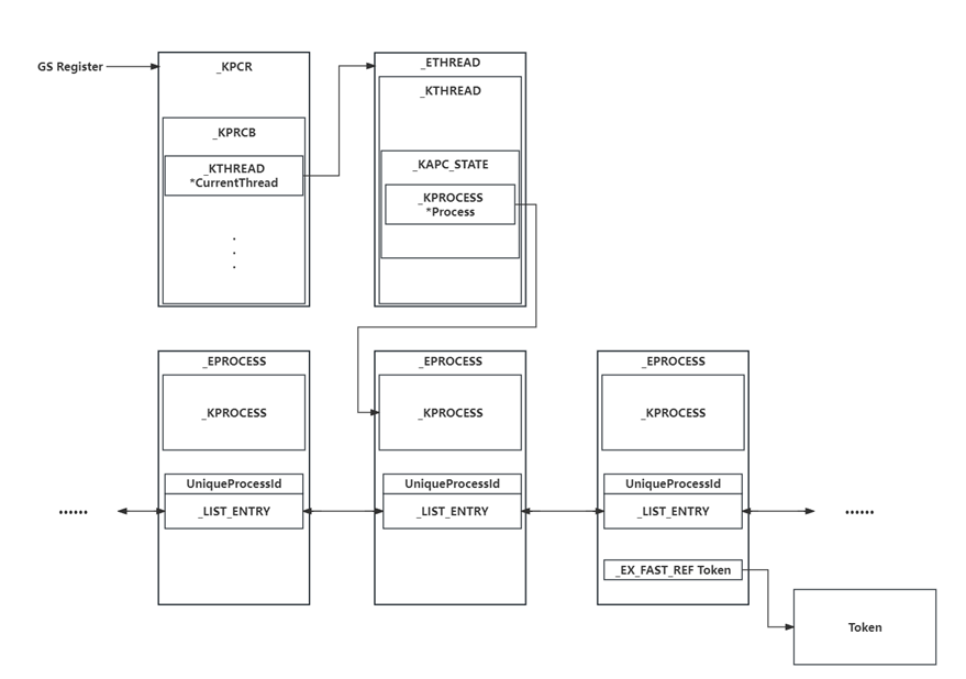
In the Windows NT kernel, the _EPROCESS structure is used to represent a process, similar to task_struct in Linux. This structure stores all information about a Windows process. The _EPROCESS structures of all processes form a doubly linked list.
The kernel-mode GS register points to the Processor Control Region, similar to the .percpu section in Linux. It contains a pointer to the current thread control block, which in turn contains a pointer to the current process control block.
II. Token: Process Privilege Credential
Just as Linux uses the cred structure in task_struct to identify process permissions, the NT kernel uses the _Token structure to identify process permissions.
Under construction.
Reference
Microsoft Learn. Spark possibility.
《windows内核原理与实现》——潘爱民 著
CodeMachine - Windows Object Headers
BlackHat USA 2021 - Windows Heap‐Backed Pool
CodeMachine - Kernel Virtual Address Layout
[原创]Windows内存篇Ⅱ x64内核内存布局的迁移演变
A Syscall Journey in the Windows Kernel
AngelBoy——Windows Kernel Heap: Segment heap in windows kernel Part 1
Inside Windows Page Frame Number (PFN) - Part 1
Kernel Pool Exploitation on Windows 7 - Tarjei Mandt